
 |  |
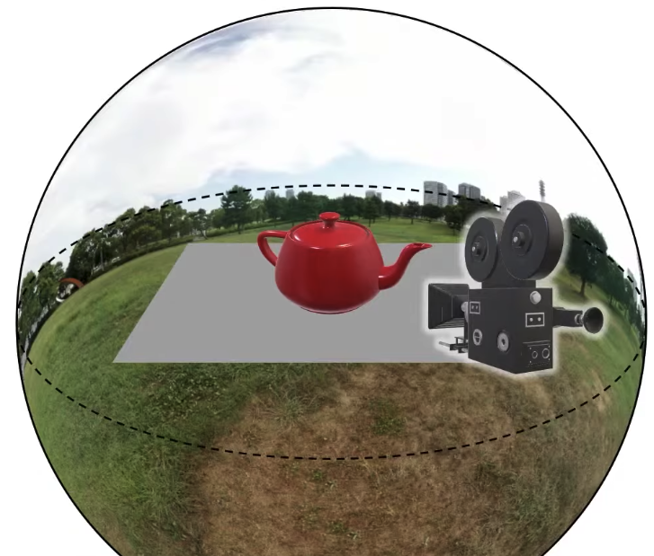
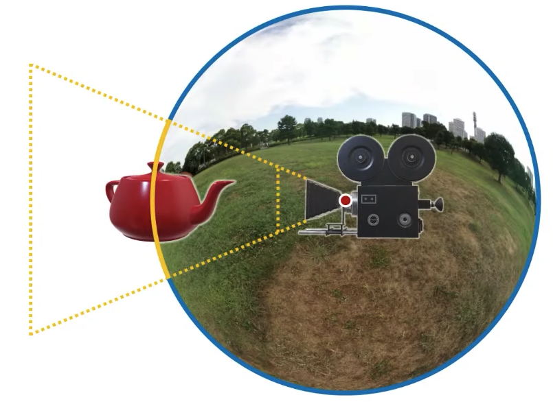
What I would like is to put this scene into some environment. So one way to do that is just containing this whole scene inside a sphere, and if I put a texture on the inside of this sphere, it’s going to give me the illusion that this scene is inside this environment. That’s what we are trying to do with environment mapping, that’s the goal.
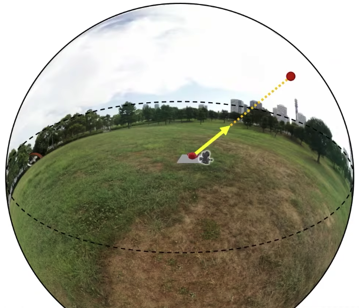
This environment is going to be far far far away, so far away that I will actually never go there. A question is that how big should this sphere be? The answer is its radius should be infinity ideally. But can I do infinity? At the very least, it needs to be very big in comparison to my scene. My scene including my camera and everything needs to be much smaller than the sphere that contains it. Now this is going to make things quite convenient actually. If I want to know the texture value at any point on the sphere, I just need to know the direction towards that point, and I don’t necessarily need to know where a view vector like this originates, like this yellow one, I would like to know what that vector sees on this background sphere, I don’t need to know where this vector originates, because my scene is so small in comparison to the size of the sphere, that I assume that it always originates at the very center of this sphere. That would be a fine assumption because the radius is infinity.
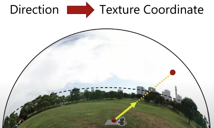
So what I would like to do is to sample the value of this environment texture at that point. So when we are using environment mapping, we’re going to be accessing the environment map using a direction only, and we’re not going to be sampling in any other way, obviously, I have some texture map on a sphere here. So what I need to do is to get this direction and somehow convert it into a texture coordinate, now how I’m going to do this will depend on how this texture is mapped onto this sphere. Obviously like whatever kind of mapping function I used, that’s going to determine how I’m going to take a direction and convert it to a texture coordinate here. For that, there are various options that people use in graphics.
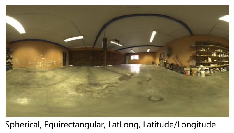
One way would be using these spherical or rectangular or latitude longitude mapping. Another way is light probe or angular format,
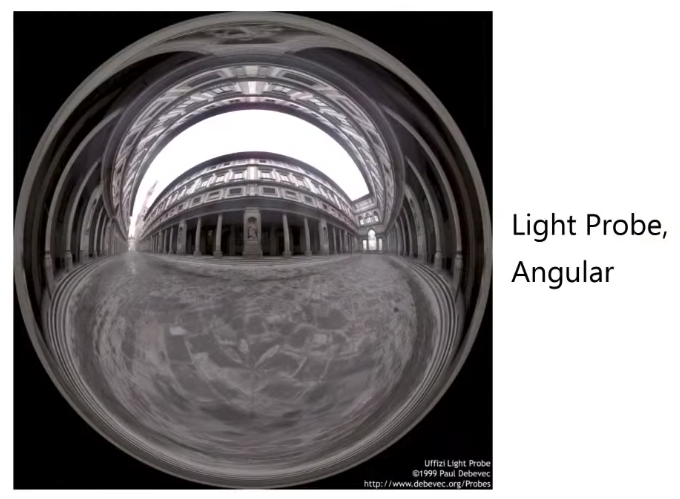 | 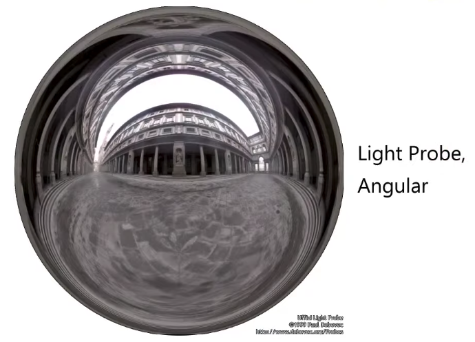 |
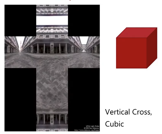
So around these edges, these maps are distorted quite a bit. I have a good density of information near the center, around the perimeter things are distorted, it’s not that an ideal mapping in that sense, but it’s quite convenient because I can just take a photo of a sphere and I get it. But often times we take some environment like this and convert it into a different format that is not as distorted. An example of that is going to be this vertical cross or this cubic mapping.
Cube Mapping
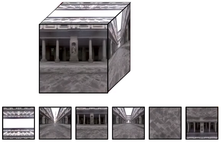
Cube maps are very very important, because cube maps are actually supported by our graphics hardware, so of all the options that we could be using for environment mapping, probably this is the most convenient option because it is actually supported by our graphics hardware and the graphics APIs.
 | 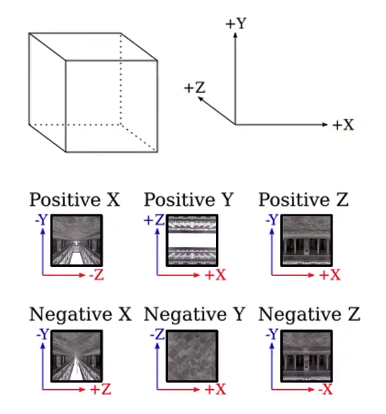 |
OpenGL uses this sort of a coordinate frame to determine the faces of the cube map. One thing to pay attention here is that this is not a right-handed coordinate system, this is a left-handed coordinate system. That’s what OpenGL uses for cube maps.
Now how to generate a cube map in OpenGL.
// buffer and binding
GLuint texID;
glGenTextures(1, &texID);
glBindTexture(GL_TEXTURE_CUBE_MAP, texID);
glTexImage2D(
    GL_TEXTURE_CUBE_MAP_POSITIVE_X,
    0,                              // mipmap level 0
    GL_RGBA,                        // internal format
    width,                          // image width
    height,                         // image height
    0,                              // border (must be 0)
    GL_RGBA,                        // format
    GL_UNSIGNED_BYTE,               // data type
    image_data                      // pixel array data
);
glTexImage2D(
    GL_TEXTURE_CUBE_MAP_NEGATIVE_X,
    ...
);
glTexImage2D(
    GL_TEXTURE_CUBE_MAP_POSITIVE_Y,
    ...
);
glTexImage2D(
    GL_TEXTURE_CUBE_MAP_NEGATIVE_Y,
    ...
);
glTexImage2D(
    GL_TEXTURE_CUBE_MAP_POSITIVE_Z,
    ...
);
glTexImage2D(
    GL_TEXTURE_CUBE_MAP_NEGATIVE_Z,
    ...
);

// mipmap
glGenerateMipmap(GL_TEXTURE_CUBE_MAP);

// filter parameter
glTexParameri(GL_TEXTURE_CUBE_MAP, GL_TEXTURE_MIN_FILTER, GL_LINEAR_MIPMAP_LINEAR);
glTexParameri(GL_TEXTURE_CUBE_MAP, GL_TEXTURE_MAG_FILTER, GL_LINEAR);

// bind and use it
glActiveTexture(GL_TEXTURE0);
glBindTexture(GL_TEXTURE_CUBE_MAP, texID);
One more thing that is specific to cube mapping, is that I can enable this global flag, this does something interesting, remember bi-linear filtering, with bi-linear filtering even with mip-mapping we are doing some sort of bi-linear at different mip-map levels, with bi-linear filtering, I need to access 4 texels around the point I am trying to sample, this is totally fine within any face, but my direction is such that I am at one of the edges, or the corners, very close to one of the edges, then the 4 texels near that position may be in two different faces, so I’m along one of the edges, then the 4 texels or 2 of them will be on one face and the other two will be on the other face. If you enable this flag, our GPU will automatically filter across these edges, so it will do bi-linear filtering, across the edges properly by taking 2 samples from one face and 2 samples from the other face, of course, this is not as cheap as sampling within a face, there’s going to be some cost associated with it, that’s why we have this global flag. So if you want to keep things as fast as possible, you turn it off, but if you want to get nice quality and you don’t want to see where these images come together, you need to enable this flag. So enable this flag is highly recommended.
glEnable(GL_TEXTURE_CUBE_MAP_SEAMLESS);Environment Rendering
I am going to render the environment map, how am I going to do that? Obviously, I am going to render my object and I need to figure our a way to render the background now, I can’t just say here the cube map and just put it in the background, or I can’t just say I’ll clear the background with this texture, you kind of need to figure out which directions on this texture to sample and what now requires some computation. So I am going to need to run some sort of a fragment shader for each one of these background pixels, I am going to write it probably very simple fragment shader, and that will need to run for each one of these pixels here. The teapot is occupying only some pixels, for all these other black pixels in the background, somehow I need to do something, so I get a fragment shader call, so how can we do this.
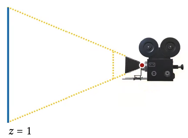
The probably simplest thing we can do we can think of right away would be just rendering a sphere around our camera. This is definitely one way of doing it, I can just render sphere around the camera so in camera space this sphere is going to be at the origin and it will have some radius, so what’s the radius of this sphere, kind like I need to figure out what the radius is supposed to be, obviously I can’t make it too small, because I definitely want the end on the sphere to be beyond my near plane, and of course it also needs to be smaller than the far plane distance. So something in between the two should work, as long as it’s in my view frustum I’ll be okay. But I am going to have other objects in this scene as well, let’s say there is a teapot right in the middle of my view frustum here, if I just render it like this, I’m going to be a little bit in trouble, so my background sphere will be occluding a part of my object, which is definitely not what I want. I want this to be in the background. So how can I avoid that.
Well, the simplest idea probably is this, I can just clear the screen, render my background, clear the depth buffer, then render my objects. So over here, I’ll be clearing my background, so what happened is that I cleared my screen I rendered the background environment, so now all the colors and pixels are having background color whatever that background image is and then I clear the depth buffer, the buffer is gone, so nothing in the background will be occluding anything now, because I cleared my depth buffer, now when I render my object, it’s going to be in front of the background, this is a solution and that works. But I am not liking this and I am not liking this at all. I am not liking this because this is rather expensive. I have this clear, so it’s going to use a depth buffer and then it’s going to clear that depth buffer again, and this is sort of unnecessary, this is not the most expensive thing, you can do obviously but there is a cost to cleaning the depth buffer. So this is not great. I want to do this without clearing the depth buffer.
glClear(GL_COLOR_BUFFER_BIT | GL_DEPTH_BUFFER_BIT);
// Draw background
...
glClear(GL_DEPTH_BUFFER_BIT);
// Draw scene objects
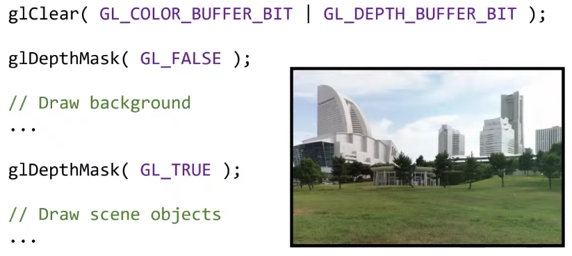
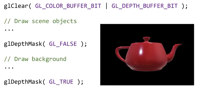
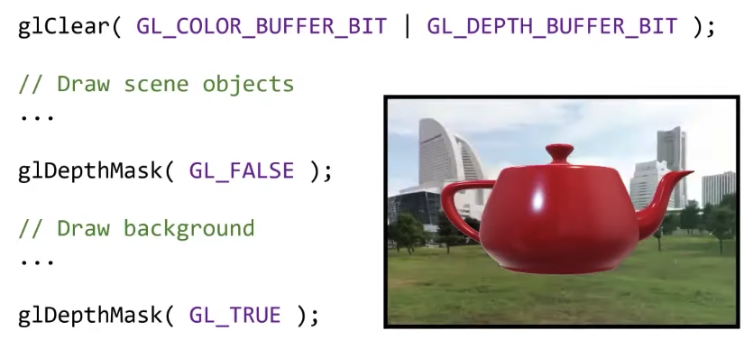
...How can I do this? Fairly easy actually. When I am rendering this background, I don’t really need a depth buffer, I don’t need any depth data from my background so how about I disable that. glDepthMask(GL_FALSE) means do not write anything to the depth buffer, so all these operations over here that they’re not going to be modifying a depth buffer at all. And then I am enabling the depth buffer right back again. So I contain my background drawing between these two disable depth of writing and enable depth of writing. So my background rendering is not going to be touching the depth buffer, and I am done.
glClear(GL_COLOR_BUFFER_BIT | GL_DEPTH_BUFFER_BIT);
glDepthMask(GL_FALSE);
// Draw background
...
glDepthMask(GL_TRUE);
// Draw scene objects
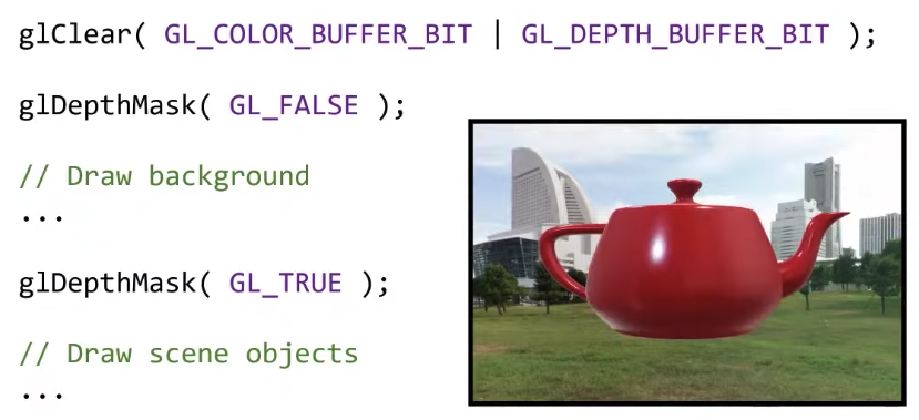
...This solution works. Now what I am not liking here is a sphere, so it’s not like I have a sphere primitive on my GPU, I can just say here’s a sphere, and just render it, a sphere is defined very easily, it’s just a position for its center and a radius. But if I am going to use rasterization for a sphere, I am going to have to triangulate it, triangle a sphere? there is going to be a lot of triangles. Maybe not millions, but still unnecessarily many triangles. How about I do something simpler than a sphere, does it have to be a sphere? It really doesn’t have to be. How about we use a cube?
 |  |
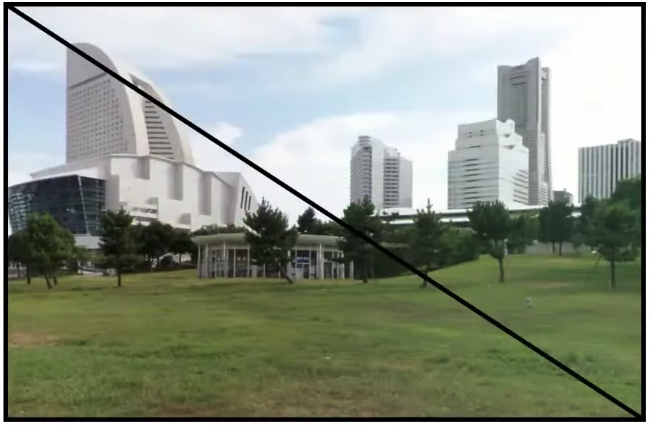
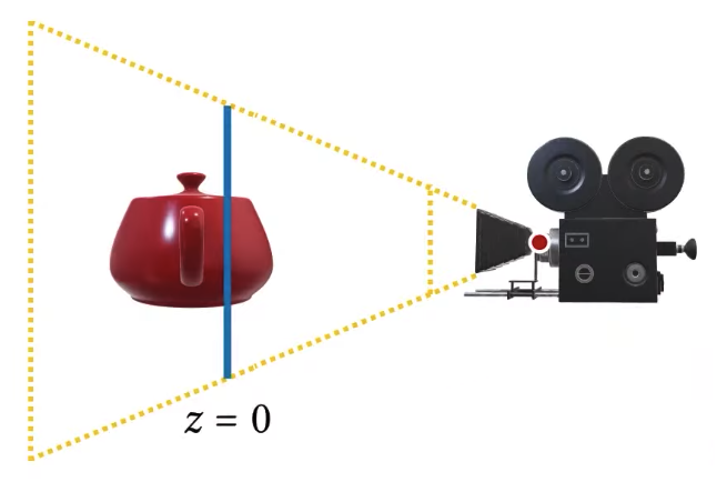
I have this cube, and I can place this cube in the world coordinates, such that when I rotate my camera, what’s going to happen is that in camera space, the cube is going to rotate. So it’s sort of automatically figuring out where it’s looking at. So based on the positions of this cube vertices. I can determine the direction from the center to that direction in world space, I can use that direction for sampling my cube map texture, and this works perfectly fine. This is probably one of the easiest ways of rendering the environment, but it’s not going to be the most efficient way of rendering the environment, we can do better than this. Now as you can see, I probably don’t need some of the faces of this cube, so this cube has 6 faces, each face will have two triangles, so I’m working with 12 triangles, I probably don’t need 12 triangles, now some of this triangles will be behind the camera obviously. I may need more than one, I actually don’t know how many I will need exactly, that depends on the camera angle, but some of them I definitely will not need. So what is my problem, my problem was that I needed a fragment shader to run for each pixel of my canvas, how about I draw something like a plane in front of my camera, can I do that? I can do that, actually, that’s fairly easy, so imagine this canvas that we’re rendering, so on this canvas, I can just draw two triangles like this and just put the texture map on that and I’m done.
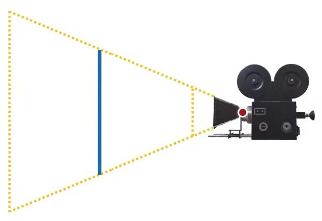 |  |  |
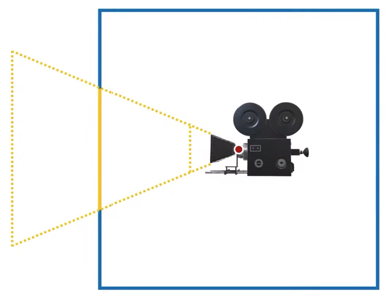
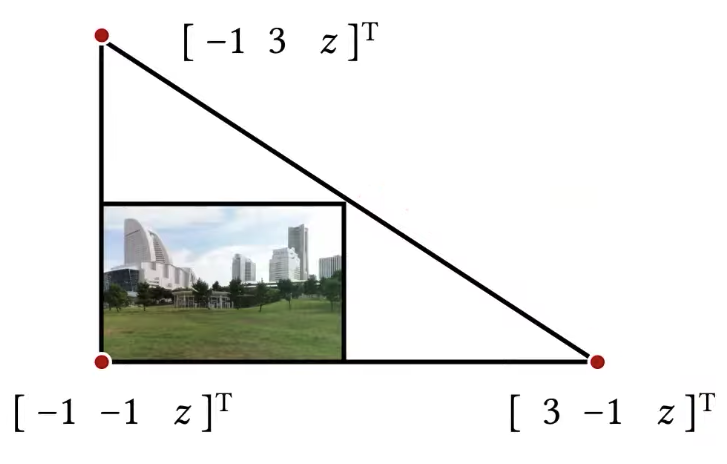
How am I going to do this like I am going to figure out where to place these triangles so they will be exactly in front of my camera? Now if you try to figure out exactly where you’re supposed to put these triangles in world space, such that they will be in front of your camera, that might be a little bit tricky, but if I specify the vertices of these triangles in the canonical view volume, that’s going to be fairly easy. Because in what we/the OpenGL call the clip space, that’s the canonical view volume in clip space, these vertices will be like this:
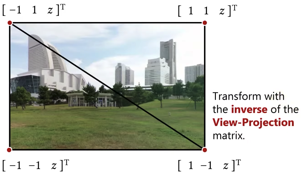
The z value doesn’t matter. What I need to do is to figure out what world space directions each one of these vertices will correspond to. I need to know the world space directions from camera to those points that these clip space positions will correspond to. Now if I drew the alternative, I was drawing a cube around the camera, in that case, I could tell what the world space directions would be for each vertex of a cube. Over here I am specifying them in the clip space, because I am specifying them in the clip space, I need to convert these clip space positions to world space directions, and I am using those directions for sampling my environment map. So what I need to do is that I need to transform them using the inverse of the view projection matrix. What I mean by this? I am going to be using the inverse of the projection because I want to go from clip space to camera space, remember the projection matrix brings you from the camera space to the canonical view volume or the clip space, I would like to do the opposite of that, I want to go from my clip space back to the camera space, so it’s going to be inverse of the projection. I also need the inverse of the view matrix, remember the view matrix is a transformation from the world coordinates to the camera coordinates or the view coordinates, so that was my view matrix, so I need the inverse of that as well. So the matrix that transform from the world space all the way to the clip space including the projection, I need the inverse of that matrix, and any translation components, I don’t care, I only care about the direction.
One obvious question is that what is this z value? zero? That’s okay. I can do -1, 1 as well.
 |  |
DirectX used to use left-handed coordinate system for pretty much everything.
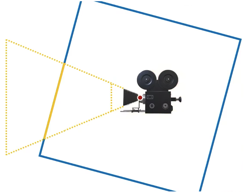
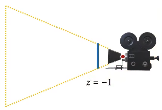
Actually, the positive 1 position is now okay. This might look ideal, but it isn’t. it’s not ideal, because z equal to 1 will be just outside of our view frustum, we need to bring it back just a little bit.
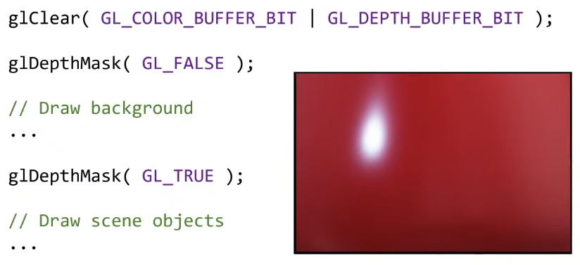
So in this case, we are rendering the environment, I am clearing the screen, disabling depth write, and then rendering background, and then I’m enabling the depth write again, so that I can draw my scene properly. So in this case, it doesn’t really matter which z value that I pick, because for my canvas, I am starting with clearing and then I am drawing my environment as my background and while drawing the environment I disabled the depth writes, so it doesn’t really matter which depth value I use for drawing this, I am going to get the same thing. And then after I am done, I am drawing my objects.
 |  |  |
Now here is one thing that is not quite ideal. Do you see that I computed some pixels twice? All the pixels that are covered by my teapot, I had to compute them twice, I compute them once as background pixels, and then I compute them again for the teapot. Remember that in interactive real time rendering, performance is very very important. This may not be a big deal when rendering the teapot, but if you’re trying to get a rendering system that’s going to be using every little bit of your GPU power, you kind of need to think about every little thing that you can save. So this is wasted computation that I did not have to do. But I did it because this is how I was rendering. It’s not very expensive but it is unnecessary. It would be much better if I only computed the background for the pixels that I was seeing the background. Imagine that you zoomed in, and you’re only seeing the part of a teapot and the entire background is not visible at all, I am just seeing the teapot now, I don’t see the background, do I still have to pay the cost of rendering them, it’s not that expensive, just a couple of triangles, but beyond these triangles, I am sampling my background environment map, and that’s going to have a cost, that’s going to bring some data from the GPU memory, it’s not free in any way, so I should get rid of it. How?
 |  |
The way to get rid of it would be reversing the order of this rendering. So if I were to render the teapot first but that’t my first scene first. And then I tried to draw the background after I draw the teapot, then my fragment shader for the background would only run for pixels where the background will be visible, for all the pixels where my teapot is visible, my background is not going to be visible and my fragment shader for the environment map will not be called. So if I want to do that, what do I do? I draw the teapot, and then maybe I draw this background far enough away that it’s not going to interfere with my teapot, so in this case, it would make scene to draw my background way back here (z = 0.999), so that it’s not overlapping with my teapot. Because if I just put my background at an arbitrary position in z, then it’s going to be overlapping with my teapot.
A question here is that does it matter in terms of complexity if I use glEnable, glDisable, glDepthTest instead of glDepthMask. Enabling disabling depth test is different than enabling disabling depth writes, you might disable depth tests, but when you’re rendering you still write to the depth buffer, just disabling that tests will disable the visibility test, we’ll disable which triangle should be in front, so the triangle you draw last will be drawn on the frame buffer including the depth buffer, so you’ll still be writing to the depth buffer, which is not something that we want.
So we are drawing two triangles for the background, can we do better? Yes, we can draw only one triangle like this. Remember that all of our transformations that we’ve been using from going to and from the clip space, they are all linear transformations, so it’s okay to pick points that are outside of this clip space, that’s perfectly fine, the linear transformation will transform linearly and you won’t be in trouble for picking positions that are outside of the clip space, just need to do the same thing, just transform them using the same inverse view projection matrix, and you’re done. You basically do the same thing as you did with the two triangles, but instead of picking two triangles you just pick one triangle that looks like this and you are done. Of course, this is not the only triangle that does this, there are other triangles you can think of anything that is large enough where everything is contained would be fine. Fairly easy to pick a triangle in clip space.
|  |
[Note: Contents come from Professor Cem Yuksel’s Interactive Graphics course, check out his website for more details]